New Products
-
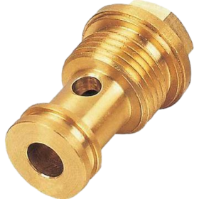
Custom Turn-Mill Combination brass parts
-
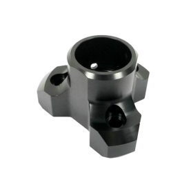
Custom Turn-Mill Combination parts
-
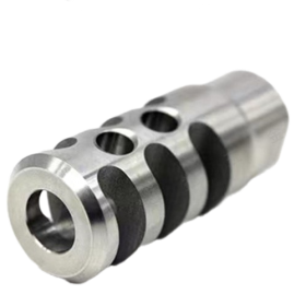
Precision CNC Turning Parts Stainless Steel shaft accessories
-
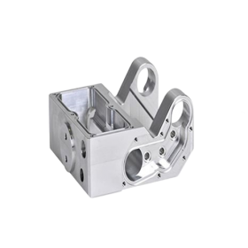
Custom CNC Milling Automated Machinery and Equipment Parts
-
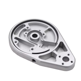
OEM/ODM Custom High Precision Metal CNC Machining/Milling/Turning Service CNC Turning Part
-
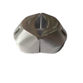
Precision CNC Milling Robotic Arm parts
Guide to CNC Machining Surface Roughness
In the intricate world of CNC machining, surface roughness stands as a pivotal factor that can make or break the performance and quality of machined parts. It is not merely a technical detail but a characteristic that permeates every aspect of manufacturing, from functionality and aesthetics to cost and production time.
1. What Exactly is Surface Roughness?
Surface roughness is a quantitative measure of the texture adorning the surface of a part post-machining. It encapsulates the microscopic irregularities and deviations that inevitably emerge during the material removal process executed by CNC machining tools. These tools, through a series of repetitive cuts, scrape away material from the workpiece surface, with the combined effects of tool movement, workpiece dynamics, and other elements conspiring to create a topography of peaks and valleys at a microscopic scale. In the context of CNC machining, we refer to the surface texture either as it emerges from the primary machining operation or after initial finishing procedures like blasting and polishing.
2. Quantifying Surface Roughness: The Metrics That Matter
To bring clarity and precision to the concept of surface roughness, a suite of metrics has been established. These metrics serve as the language through which engineers and manufacturers communicate the nature of surface irregularities.
· Ra (Average Roughness): Arguably the most ubiquitous metric in CNC machining and manufacturing at large, Ra represents the arithmetic mean of the surface height deviations measured from the mean line over a specified distance. Picture the mean line as the “equilibrium” between the peaks and valleys of the surface profile; the average height of the peaks above this line gives us the Ra value. Measured in µm (micrometres), a lower Ra indicates a smoother surface with fewer height variations, while a higher Ra betokens a coarser, more textured finish.
· Rz (Average Maximum Height): This metric zeroes in on the average maximum height of the surface irregularities. It is calculated as the mean of the vertical distances between the highest peaks and the lowest valleys within a given length, providing a snapshot of the overall “extremes” of the surface topography.
· Rp (Maximum Profile Peak Height): As the name suggests, Rp pinpoints the tallest peak’s height from the mean line over a specified sampling length, highlighting the most prominent upward deviation on the surface.
· Rv (Maximum Profile Valley Depth): In contrast, Rv delves into the deepest valley, measuring its depth from the mean line over the same sampling length, thus revealing the most significant downward excursion.
· Lay (Texture Direction): Lay describes the dominant direction in which the surface irregularities are aligned. It offers insights into how the surface texture is oriented, which can be crucial for certain applications where directional properties matter, such as in fluid flow or wear patterns.
3. The Indispensable Significance of Surface Roughness
3.1 Functionality and Performance
· Contact and Friction: In scenarios where parts need to maintain a firm grip or non-slip contact, such as in fitted assemblies or hand-held components, an appropriate level of surface roughness is essential. It provides the necessary friction to prevent slippage. However, in moving, vibrating, or load-bearing mating parts like joints, bearings, and assemblies, excessive roughness can spell trouble. The increased friction not only resists motion, leading to higher energy consumption and heat generation but also accelerates wear and tear. Striking the right balance, with a relatively low surface roughness, is key to minimizing these detrimental effects and enhancing wear resistance. Interestingly, a certain degree of roughness can also be beneficial, as the grooves it creates can trap lubricants, ensuring better lubrication in dynamic systems.
· Coating Adhesion: When it comes to applying coatings to a surface, surface roughness plays a starring role. The microscopic grooves and valleys on a rougher surface act as reservoirs, entrapping coating substances and promoting better absorption and retention. This enhanced adhesion is vital for coatings to perform their intended functions, whether it’s for corrosion protection, aesthetics, or other specialized applications.
· Electrical Conductivity and Other Properties: Surface roughness can also influence electrical conductivity, with smoother surfaces generally offering lower resistance. In addition, it impacts sealing and leakage prevention, sanitation (as in the case of medical or food processing equipment), and optical properties. For instance, in optical components, a precisely controlled surface roughness is necessary to avoid light scattering and interference.
3.2 Aesthetics and Visual Appeal
The visual allure of a machined part is directly tethered to its surface roughness. Glossy, mirror-like finishes that demand attention, as seen in jewelry or high-end decorative pieces, necessitate a surface roughness of 0.8 µm Ra and below. The fewer the surface irregularities, the more efficiently light reflects off the surface, bestowing it with a lustrous sheen. Conversely, if a textured or matte look is the desired aesthetic, a surface roughness of 1.6 µm Ra and above can be specified to create the desired visual effect.
3.3 Cost and Production Efficiency
Achieving a particular surface roughness level is not without its economic implications. Smoother surfaces, especially those with Ra values of 0.4 µm Ra and below, demand meticulous machining efforts. This often entails slower machine speeds, finer feeds, and shallower cuts, all of which translate to increased production time and cost. Additional post-processing operations like grinding, polishing, or lapping may also be required, further adding to the expense. Manufacturers must carefully weigh the benefits of a specific roughness level against the associated costs to optimize production.
4. CNC Machining Surface Roughness Levels: A Closer Look
CNC machining surface roughness is predominantly gauged by the average roughness (Ra), with manufactured parts typically spanning a range from 0.1 µm Ra to 6.3 µm Ra, signifying the spectrum from smooth to rough. However, technology has pushed the boundaries, and in specialized fields like semiconductor manufacturing, silicon wafers can achieve an astonishing 0.01 µm Ra.
Most CNC machining custom manufacturers offer a selection of standardized surface roughness levels to cater to diverse needs:
· 3.2 µm Ra: This is a standard commercial machine finish compatible with most consumer parts. Although it has visible cut marks, 3.2 µm Ra is the default surface roughness machinists apply on the CNC part.
· It is the ideal surface roughness for machined parts exposed to vibrations, stress, and loads. Also, it is recommended for mating moving surfaces where the load is light and motion is slow. Examples include structural machine brackets, automotive engine covers, general tooling fixtures, and machine chassis.
· 1.6 µm Ra: 1.6 µm is the industry standard roughness level for general applications. It has slightly visible cut marks and is ideal for machinery components or mechanical parts where the surface finish influences performance less critically. It is a perfect surface roughness for slow-moving and light load-bearing surfaces instead of fast-rotating parts and those exposed to intense vibration. Applications encompass hydraulic piston rods, slow-speed gearboxes, precision fasteners, and electronic housings.
· 0.8 µm Ra: 0.8 µm Ra is a considerably high-grade surface roughness that requires extremely close control. Although it costs more, it suits parts subjected to stress concentration, especially in automotive and consumer electronics applications. Besides, it can also be used for bearings in cases involving occasional motion and light loads. Notable applications are found in precision gears for robotics, hydraulic valve components, medical device housings, and jewelry components, where the smoother surface is crucial for performance and aesthetics.
· 0.4 µm Ra: Regarded as the zenith of smoothness in most manufacturing settings, this level is devoid of observable cut marks. It demands painstaking, closely controlled machining followed by polishing, a process that can escalate production costs by up to 15%. Reserved for rapidly moving or vibrating mating parts and those under high tension and stress, it finds its niche in high-precision bearings for aerospace or high-speed machinery, pneumatic cylinder rods, optical components, and precision injection molds.
5. Mastering the Art of Achieving Desired Surface Roughness
5.1 Machining Parameters: The Precision Trio
· Cutting Speed: This parameter, measured in metres per minute and dictated by the spindle speed (RPM) and tool diameter, wields significant influence over surface roughness. A higher cutting speed, thanks to the conservation of angular momentum and the gyroscopic effect, can stabilize the tool or workpiece, reducing vibrations and yielding smoother cuts. However, caution must be exercised, as excessively high speeds can trigger increased friction, leading to a rougher finish.
· Feed Rate: The rate at which the cutting tool advances into the workpiece is a critical determinant of surface texture. A slower feed rate affords the tool more time per unit area to meticulously remove material, translating to a finer surface roughness.
· Cut Depth: The depth to which the cutting tool penetrates the material’s surface per cutting pass is another factor to reckon with. Deeper cuts tend to induce more vibrations and tool deflection, as the tool is engaging a larger surface area, often resulting in a rougher surface. In contrast, shallower cuts are conducive to achieving a more refined CNC surface finish.
These parameters are not set in stone; rather, they require careful calibration and a judicious mix-and-match approach, taking into account variables such as the machining process and the material being worked on. Manufacturers and engineers rely on mathematical formulas and empirical knowledge to fine-tune these parameters and hit the bullseye in terms of desired surface roughness.
5.2 Cutting Tool: The Sharp Edge of Precision
· Tool Geometry: The shape, angle, and sharpness of the cutting tool are instrumental in sculpting the surface roughness. Tools with large rake angles and razor-sharp edges are more likely to glide smoothly across the workpiece, leaving behind a smoother surface in their wake.
· Tool Wear: As tools age and wear, they lose their edge – literally. Worn tools make uneven contact with the workpiece, leading to erratic cutting actions and heightened friction, all of which conspire to roughen the surface.
· Tool Material: The choice of tool material is a strategic decision that can tip the scales in favor of a smoother finish. Harder materials like carbide, diamond, and tool steel possess the strength and resilience to overcome the workpiece’s resistance to cutting, translating to reduced surface roughness.
5.3 Machining Conditions: The Invisible Hand
· Machine Movement: A CNC machine that quivers or shifts during operation can introduce unwanted surface irregularities. Unbalanced spindle rotation or other improper movements can disrupt the cutting process, marring the surface smoothness. Ensuring the machine’s stability and precision is paramount.
· Workpiece Alignment and Positioning: Even the slightest misalignment between the tool and the workpiece can set off a chain reaction of surface defects. Proper clamping and positioning using jigs and fixtures are non-negotiable steps in the pursuit of the desired surface roughness.
· Temperature Control: The heat generated by friction during cutting can cause the workpiece to expand, throwing off the carefully planned surface roughness. Employing cutting fluids to regulate temperature is a tried-and-true method to keep things on track.
5.4 Machinability: The Material’s Voice
The machinability of a material, a complex interplay of its various properties, has a say in the final surface roughness.
· Hardness: Materials that put up a stiff fight against cutting and abrasion can set off vibrations in the cutting tool and ramp up friction, leaving behind a rougher surface as a calling card.
· Thermal Expansion: When a workpiece expands due to friction-induced heat, it can disrupt the cutting process, leading to uneven surfaces.
· Work Hardening: The shear stress and plastic deformation endured by the workpiece during cutting can trigger strain hardening in some materials, compounding the hardness issue and further affecting surface roughness.
5.5 Post-Processing: The Finishing Touch
In many cases, the as-machined surface finish falls short of the desired surface roughness. This is where post-processing operations step in to save the day.
· Grinding and Polishing: A two-step dance that involves using progressively less abrasive polishing compounds and tools to even out surface irregularities. With each pass, the surface becomes smoother, and with enough perseverance, a mirror-like finish can be achieved. However, this pursuit of perfection may come at the cost of dimensional accuracy.
· Bead Blasting: Picture a stream of abrasive particles hurtling towards the surface, etching a matte, grainy finish. While it imparts a unique texture, the final result can be somewhat unpredictable, as it hinges on factors like blasting media grit and operator skill.
· Brushing: Using grit to polish the material in a single direction, brushing imparts a unidirectional satin finish. It typically offers a CNC machining surface roughness of around 1.2 µm Ra, making it a popular choice for aesthetic enhancements.
6. Measuring Surface Roughness: Unveiling the True Texture
To ensure that the machined surface roughness aligns with expectations, measurement is the watchword. There are several techniques at the disposal of manufacturers:
· Contact Profilometers: These trusty devices employ a highly sensitive diamond-tipped stylus to traverse the specimen’s surface, meticulously recording microscopic irregularities. The stylus’s journey across the surface culminates in the calculation and display of Ra and other roughness values. While accurate, they can be time-consuming and carry the risk of scratching the delicate surface.
· Non-Contact Profilometers: Operating sans stylus, these devices harness technologies like laser triangulation, digital holography, interferometry, or confocal microscopy to scan the surface. They offer a faster alternative and eliminate the risk of damage, making them ideal for measuring fine, delicate surfaces.
· Atomic Force Microscopy (AFM): When nanometer-level precision is the order of the day, AFM steps up to the plate. Using a sharp probe to scan the surface, it not only provides insights into surface roughness but also delves into other properties like magnetic and mechanical characteristics.
· 3D Scanning: For a more comprehensive view of the surface topography, 3D scanning technologies create detailed maps, enabling roughness measurement across larger areas. This approach demands sophisticated equipment but offers a wealth of information.
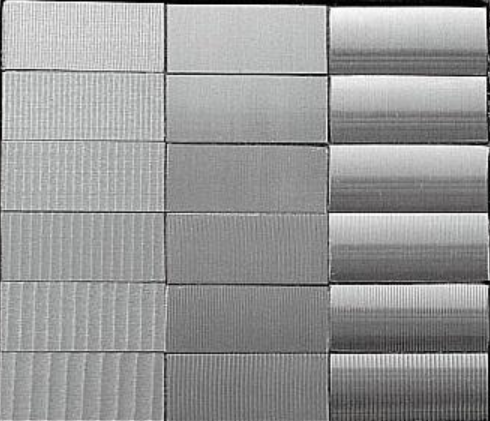
· Comparison to Roughness Standards: In less formal settings, a simple visual comparison of the machined part to pre-calibrated roughness specimens can provide a quick estimate. While not as precise as the other methods, it serves its purpose in non-critical situations.
7. Aluminum Alloy Surface Treatment: A Complementary Realm
Aluminum alloys, with their unique blend of properties, are prime candidates for CNC machining. However, to truly unlock their potential, surface treatment is often the key.
7.1 Overview of Surface Treatment
Surface treatment for aluminum alloys is a multi-faceted process that begins with mechanical and chemical treatments to form a protective layer on the surface. This layer not only shields the alloy from the vagaries of nature, enhancing its corrosion resistance, but also elevates its aesthetic appeal, adding value to the end product. The process typically encompasses pre-treatment, film formation, and post-film treatment, with pre-treatment involving a combination of mechanical and chemical procedures.
· Mechanical Treatment: Spraying, shot blasting, grinding, polishing, and waxing are among the tools in the mechanical treatment arsenal. These processes are designed to level the playing field, eliminating surface imperfections and preparing the alloy for further treatment.
· Chemical Treatment: This step is all about laying the foundation for successful coating. By removing oil, rust, and other contaminants, and creating a reactive surface, chemical treatment ensures that the film-forming material adheres tenaciously, maximizing the protective and decorative potential of the coating.
7.2 Common Surface Treatments for Aluminum Alloys
· Chromization: This specialized process deposits a thin yet potent chemical conversion film, typically ranging from 0.5 to 4 µm in thickness, on the aluminum alloy surface. The film’s excellent adsorption properties make it a prime candidate for serving as a coating base, especially in electronic applications where conductivity is crucial, such as in mobile phone battery conductive strips and magnetoelectric equipment.
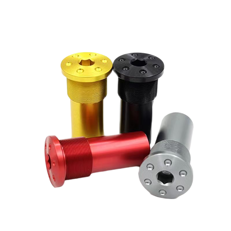
· Anodizing: A cornerstone of aluminum alloy surface treatment, anodizing creates a uniform and dense oxide layer. This layer can significantly boost the surface hardness, with standard anodizing reaching 200 - 300HV and hard anodizing scaling heights of 400 - 1200HV. Beyond hardness, it offers a kaleidoscope of colors, making it a favorite for applications ranging from automotive and aerospace to consumer electronics. The anodizing process can be tailored to produce single or dual colors, with precise steps involving polishing, sandblasting, degreasing, anodizing, dyeing, sealing, and drying.
· Electroplating: For aluminum alloys that need a boost in properties like hardness, wear resistance, and conductivity, electroplating is the answer. By depositing a layer of a different metal, electroplating can transform the alloy’s surface characteristics, making it more suitable for a wide range of applications, from decorative finishes to industrial components.
· Powder Spraying: Using electrostatic forces to attract powder coating to the aluminum alloy surface, this method offers a cost-effective and color-rich solution. After baking, the powder coating forms a durable finish that can mimic a variety of textures, from high-gloss to matte, and even imitate wood grain, making it a popular choice for architectural and furniture applications.
· Sandblasting: Harnessing the power of compressed air and abrasive particles, sandblasting can transform the surface texture of aluminum alloys. It can create a matte finish, remove burrs, and enhance the overall aesthetic, giving the alloy a more refined look.
· Polishing: Whether through mechanical or chemical means, polishing is dedicated to reducing surface roughness, achieving a mirror-like finish that not only looks good but also improves the alloy’s dimensional accuracy and geometric shape precision.
· Electrophoresis: This process allows aluminum alloys to sport a vibrant array of colors while maintaining their metallic luster. It also enhances the surface’s corrosion resistance, making it a popular choice for applications where both aesthetics and durability are prized.
· Brushing: By grinding the surface in a specific direction, brushing creates decorative lines that add a touch of elegance. It can be used to conceal minor flaws and give the alloy a non-mirror-like metallic sheen, finding applications in everything from electronics to automotive interiors.
8. Conclusion: The Harmonious Symphony of Precision and Beauty
In the grand orchestra of CNC machining and aluminum alloy surface treatment, surface roughness plays a leading role. Understanding its nuances, from measurement and quantification to the factors that influence it and the techniques to control it, is essential for manufacturers aiming to produce high-quality, functional, and aesthetically pleasing parts. By carefully orchestrating machining parameters, tool selection, machining conditions, and post-processing, and complementing these efforts with appropriate surface treatments for aluminum alloys, engineers can achieve a harmonious blend of precision and beauty, ensuring that each machined part meets and exceeds expectations. Whether it’s the smooth glide of a high-precision bearing or the lustrous finish of a piece of jewelry, surface roughness is the invisible hand that shapes the world of engineered products.


 Evan Xiao